Skip to content
g.tec medical engineering · Stimulation and triggering

g.STIMbox

Digital stimulation box

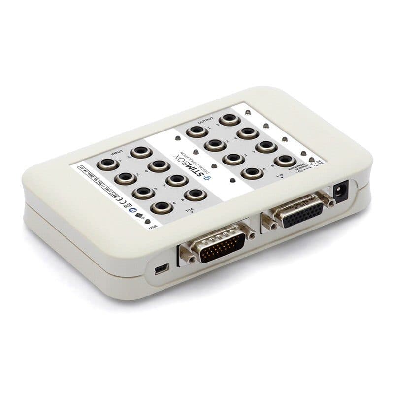
g.STIMbox generates and records trigger signals: you program a wide range of paradigms with ease and run them with high timing precision. Triggers from external devices are recorded through its 14 digital inputs, which makes it an ideal complement to electrophysiological research systems that need additional digital inputs and outputs.

  • 14 in · 16 out (TTL)
  • USB
  • C / MATLAB / Simulink
  • SSVEP stimulation
g.STIMbox digital stimulation box

Highlights

  • Microcontroller-driven inputs and outputs for high timing accuracy
  • Precisely timed experimental paradigms through the digital outputs
  • Digital inputs collected and used within the recording system
  • Direct input/output control from a computer over USB
  • Cinch (RCA) connectors on 8 outputs: LEDs, electrical or vibrotactile stimulators and devices triggered by 5 V pulses
  • SUB-D ports for multi-channel devices
  • C API, MATLAB API and Simulink drivers

Technical specifications

Digital inputs
14 (TTL)
Digital outputs
16 (TTL)
Interface
USB
Power supply
USB or external power supply
SSVEP frequency range
1–50 Hz
Software support
C API, MATLAB API, Simulink
Operating mode
Synchronous and asynchronous
Robot control with SSVEP

Four LEDs, four directions

Define four stimulation frequencies for the LEDs, for example 14, 16, 18 and 20 Hz: avoiding the alpha band and frequencies that are multiples of each other is recommended. g.HIsys collects EEG from electrodes over the visual cortex and analyses the SSVEP signals; after calibration the four LEDs move the robot forward, back, left and right. For a VEP experiment, a strobe light on a digital output gives an exact trigger between the EEG and the flash.

  • 4 stimulation frequencies
  • g.HIsys
  • VEP experiments
g.SSVEPbox

Visual stimulation for SSVEP studies

g.SSVEPbox is a visual stimulation device that connects to the digital outputs of g.STIMbox. Four ultra-bright, dimmable LEDs give precise stimulation, and four small LEDs show the active target. Flicker frequencies are set with the g.STIMbox MATLAB API; with a Simulink paradigm, training mode shows the target, and in real-time control the user selects an LED by fixing their gaze on it.

  • 4 ultra-bright LEDs
  • MATLAB API
  • Simulink paradigm
Accessories

Push button, LED box and g.VIBROstim

Small devices on single cinch connectors cover the basics: push buttons on the input channels pass subjects' responses to the recording system, and single LED boxes on the output channels provide visual stimulation. g.VIBROstim is a compact vibrotactile stimulator fixed to the limbs or trunk with Velcro or adhesive tape, for short tactile stimulation in research.

  • Push button
  • Single LED box
  • g.VIBROstim
g.tec
Contact

Let's plan your project together.

Talk to our team about device selection, protocol design, installation and software integration. We will work out the technical configuration that best fits your research or clinical goal.

Request a quote

Call us +90 554 381 46 20Serving all of Türkiye · reply within 24 hours on working days